Introduction
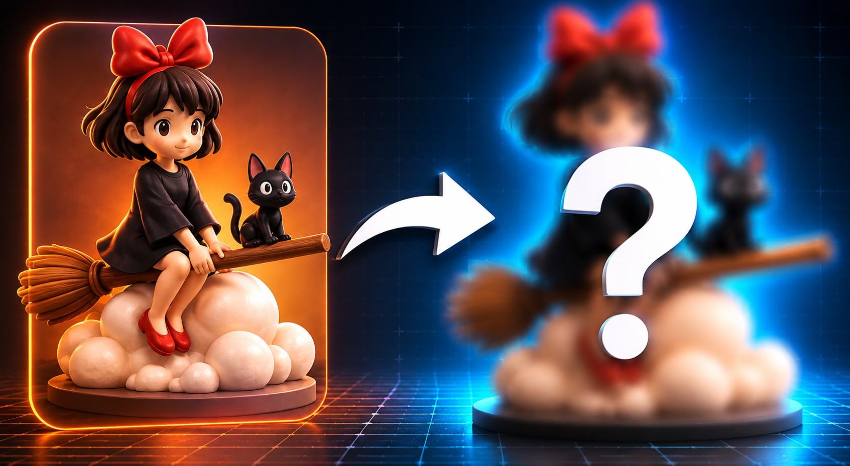
Modern AI tools can generate impressive 3D models in just a matter of minutes. However, turning that model into a physical figurine still requires a surprisingly long production process.
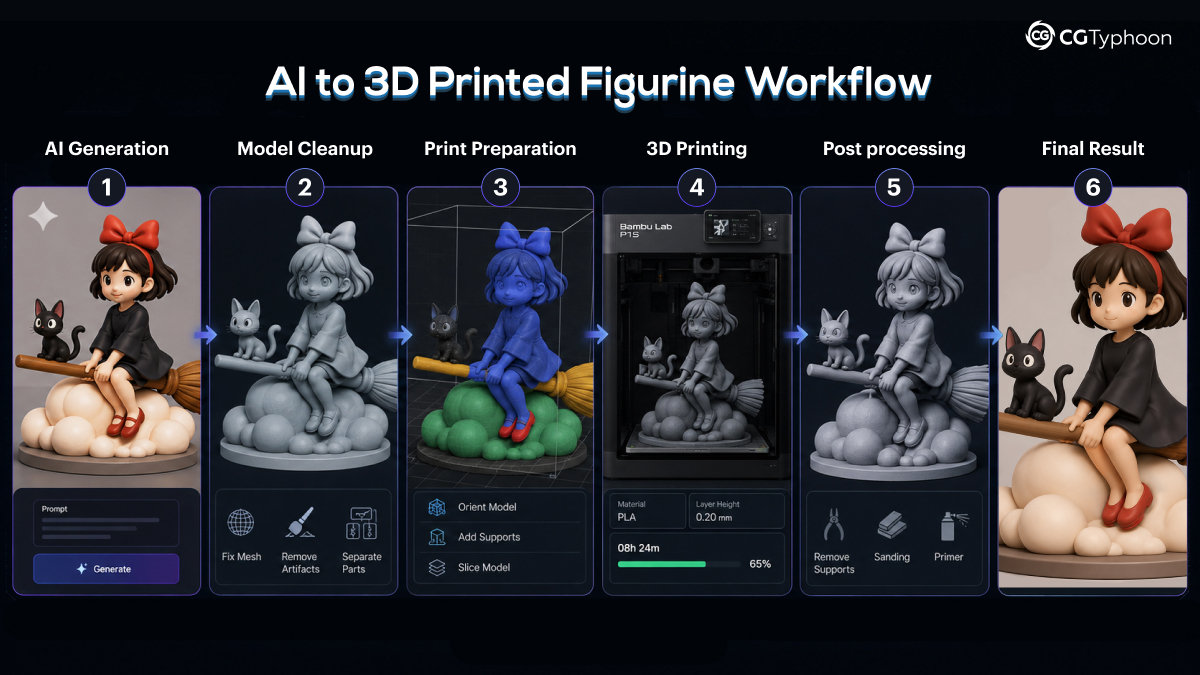
In this article, I wanted to test a complete AI-to-3D-print workflow — from concept generation all the way to a finished figurine printed on an FDM printer. My goal wasn’t simply to create a nice-looking model, but to see how well modern AI tools fit into a practical 3D printing workflow.
Along the way, I encountered many of the common issues found in AI-generated meshes:
- floating geometry
- disconnected mesh parts
- topology issues
- non-manifold geometry
- support planning challenges
- unstable center of gravity
- thin geometry
- slicing problems
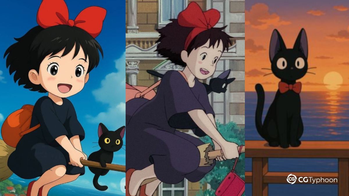
For this project, I chose Kiki and her cat Jiji from Kiki’s Delivery Service by Studio Ghibli. I’ve always loved the studio’s visual style, and the character was a great fit for this experiment thanks to her recognizable silhouette and relatively simple shapes.
When selecting a concept, I intentionally avoided overly complex characters packed with tiny details. Large readable forms and simpler geometry tend to work much better for FDM printing, making Kiki an ideal candidate for this test.
A Good-Looking Model ≠ A Printable Model
Most AI-generated models look finished at first glance. However, once you start preparing them for 3D printing, it quickly becomes clear that a visually convincing model in the viewport and a truly printable model are often two very different things.
Tools Used
| Stage | Tool |
|---|---|
| Concept Art | ChatGPT |
| Image-to-3D Generation | 3D AI Studio (Prism 3.1) |
| Mesh Cleanup | Blender |
| Sculpting & Polishing | ZBrush |
| Slicing | Bambu Studio |
| Printing | Bambu Lab P1S |
Part 1. Concept & AI Generation
Choosing the Character Concept
Before starting the project, I needed to choose a character that would not only be interesting to print, but would also work well within the limitations of FDM printing.
Knowing the constraints of FDM printers, I intentionally avoided overly complex designs packed with tiny details. For this type of workflow, it is generally better to work with:
- clear, readable silhouettes
- large primary shapes
- simplified geometry
- a stable printable structure
After browsing references on Pinterest, I settled on a stylized chibi anime aesthetic.
Characters in this style are particularly well suited for 3D printing thanks to their:
- exaggerated proportions
- simplified details
- larger support areas
- more stable geometry
In the end, I chose Kiki and her cat Jiji from Studio Ghibli’s Kiki’s Delivery Service. Besides being a longtime fan of Studio Ghibli’s work, I felt the character was a perfect fit for this experiment.
Generating the AI Concept Art
For concept generation, I used ChatGPT’s image generation capabilities.
One advantage was that I didn’t need to spend much time describing the character. A simple prompt such as:
Create a concept of a young witch Kiki flying on a broom together with her black cat in the style of a collectible figurine,
was enough to produce surprisingly good results.
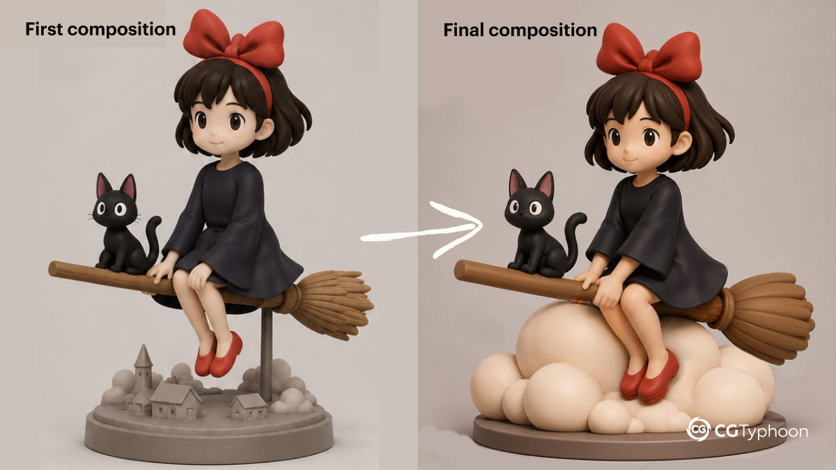
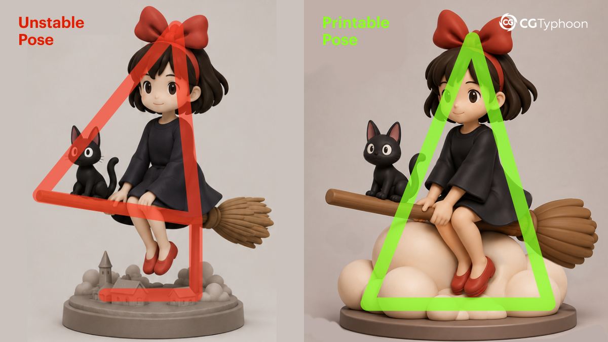
The first concepts already looked promising. However, the composition contained a potential issue for future printing: the entire character was effectively supported by a very thin section of the broom.
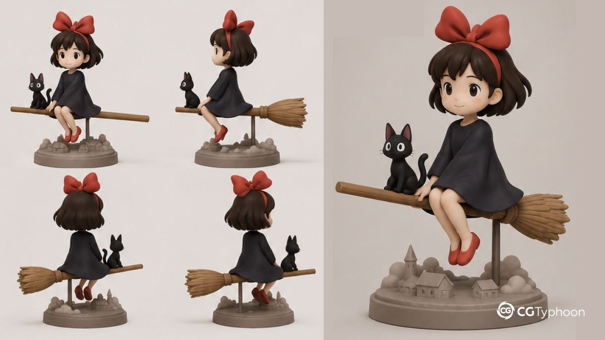
This looked perfectly acceptable in a rendered image, but for FDM printing the structure was far too fragile.
To improve both stability and composition, I decided to add a cloud beneath the character. This change:
- improved the overall composition
- added additional support points
- increased print stability
- reduced stress on supports
After several iterations, I arrived at a concept that worked both visually and structurally.
Why Support Planning Matters Even at the Concept Stage
One common misconception in AI-driven workflows is that support planning only becomes important during slicing.
In reality, printability should be considered much earlier in the process. This is especially true when working with:
- flying poses
- dynamic compositions
- thin support areas
- asymmetrical silhouettes
Thinking about stability at the concept stage can save a significant amount of time later in the pipeline.
Preparing the Concept for 3D Generation
A closer inspection of the concept revealed several typical AI-generated artifacts.
For example, one of the character’s hands was generated incorrectly. Fixing it was straightforward:
- update the prompt
- generate a corrected version
- combine the best elements from both images in an image editor
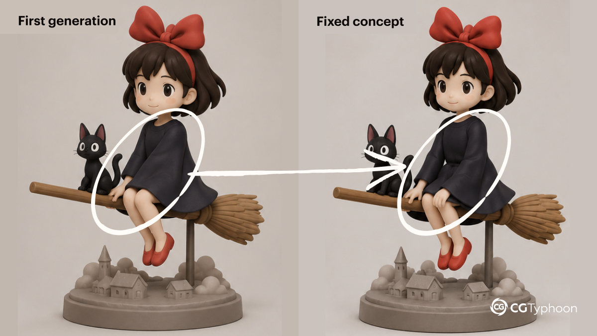
Issues like these are fairly common during AI concept generation and are usually easy to resolve with a few additional iterations.
At this stage, it is also recommended to create additional views of the character:
- front view
- side view
- back view
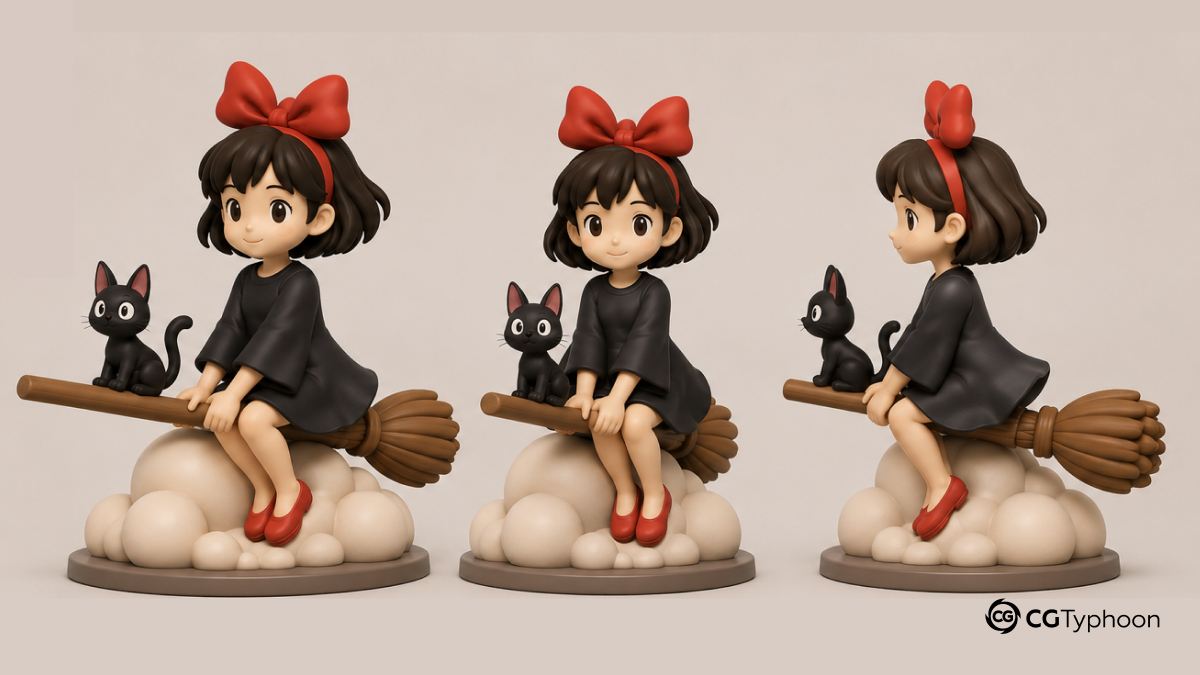
These reference images help image-to-3D models better understand the overall shape and volume of the character.
In my case, I intentionally skipped this step because I wanted to test the fastest possible workflow. In hindsight, that decision probably cost me more time than it saved. Several shape-related issues later had to be corrected manually in ZBrush, which ultimately took longer than creating the extra views in the first place. 😅
Additional Optimization for Image-to-3D Generation
In some cases, it is possible to simplify the later stages of model preparation directly at the concept stage.
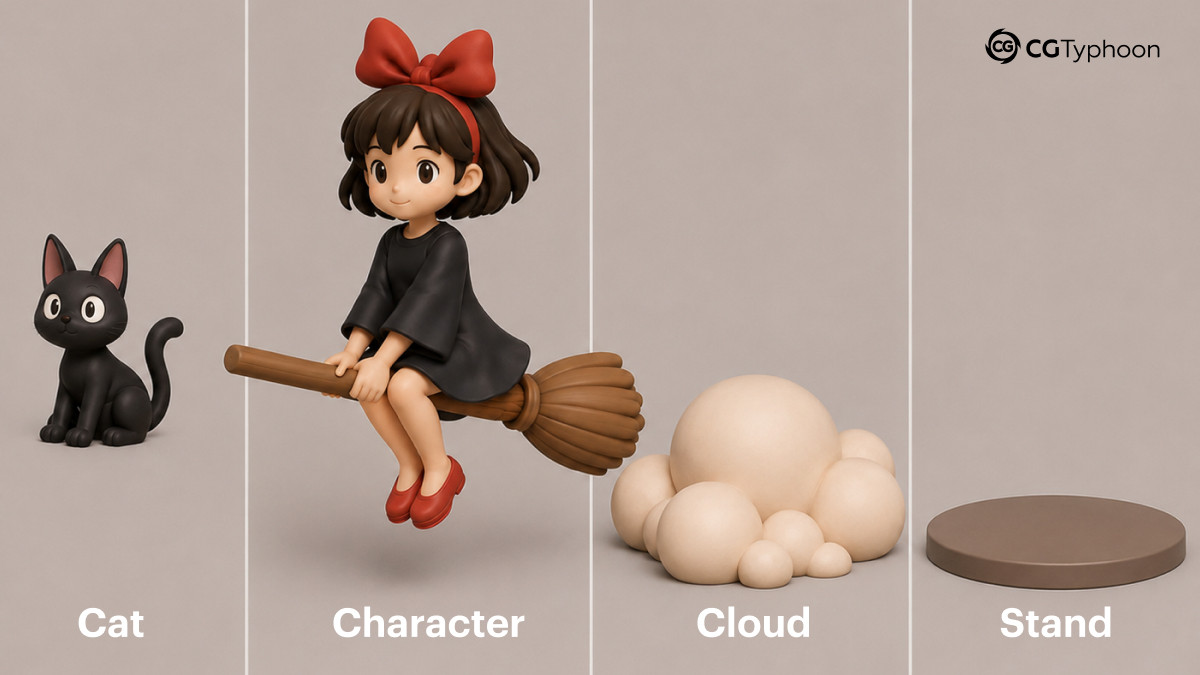
Instead of generating the entire composition as a single object, you can ask the AI to separate the scene into individual components and present them together in a single reference sheet or collage. For this project, the prompt could have looked something like this:
Separate the concept into individual parts while preserving the original proportions and pose. Show the following elements in a single image:
- the cat
- the character with the broom
- the cloud
- the display base
This approach does not guarantee perfect results on the first attempt, but it can significantly reduce the amount of manual work required later. In some cases, the generated parts are already better separated, making cleanup and preparation in Blender and ZBrush much easier.
The downside is that multiple objects need to be generated instead of a single composition. If you are working within the limits of a free plan, you may quickly run out of available generations.
For this experiment, I intentionally chose the fastest possible approach and generated the entire composition as a single mesh. While this saved time initially, it later required additional work to separate the model into printable parts and reconstruct geometry that had been hidden inside other objects.
Generating the 3D Model
For image-to-3D generation, I tested several services using only their free plans:
- Meshy AI
- Hunyuan 3D
- 3D AI Studio (Prism 3.1)
All three were evaluated using an image-to-3D workflow.
Among the tested solutions, 3D AI Studio (Prism 3.1) produced the best result.
The generated model captured the overall shape of the concept surprisingly well and provided a solid foundation for further refinement.
However, a closer inspection revealed several common issues found in modern AI-generated meshes:
- floating geometry
- disconnected parts
- chaotic topology
- intersecting meshes
- thin unsupported areas
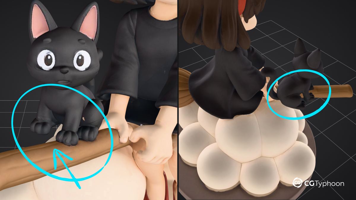
One obvious example was the cat. From the intended viewing angle, it appeared to be sitting naturally on the broom. Once the model was rotated, however, it became clear that the cat was essentially floating beside it rather than actually resting on the broom.
Additional reference views might have helped the generator better understand the character’s form and avoid issues like this. Since I skipped that step, these problems ultimately had to be corrected manually in ZBrush.
At this stage, the generated model felt more like a solid base mesh than a fully production-ready asset.
Part 2. Preparing the Model for Production
Why a Good-Looking Model ≠ A Printable Model
Modern AI tools are already capable of producing highly convincing 3D models and can dramatically accelerate the creation of a usable base mesh. For concept work, visualization, and rapid prototyping, the results are often more than sufficient.
However, once a model is prepared for 3D printing, the requirements become significantly more demanding. Successful printing depends not only on appearance, but also on geometry quality, wall thickness, proper connections between parts, structural stability, and correct preparation for slicing.
Because of this, many issues only become visible after importing the model into Blender, inspecting the mesh, generating supports, or even during the printing process itself.
This is not necessarily a limitation of modern AI generators. Rather, it reflects the difference between creating a visually convincing model and preparing a model for real-world 3D printing.
A Good-Looking Model ≠ A Printable Model
Even a visually impressive mesh may contain:
- non-manifold geometry
- disconnected parts
- floating surfaces
- broken topology
- unsupported geometry
Common Problems in Generated Meshes
While working on the project, I encountered several common issues frequently found in AI-generated meshes.
Floating Geometry
Some elements appear to be connected to the model visually, while in reality they are completely detached from the main geometry.
Disconnected Parts
Certain areas of the model exist as separate objects rather than a unified structure, which can create problems during preparation for printing.
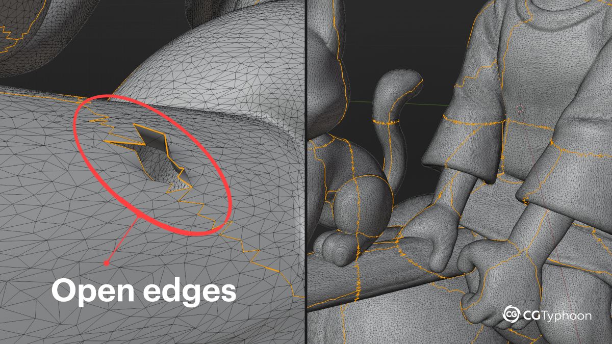
Non-Manifold Geometry
Non-manifold geometry occurs when the mesh becomes ambiguous for the slicer. This can lead to support-generation errors, missing surfaces, or incorrect layer generation.
Chaotic Topology
Generated meshes often feature highly uneven topology, with excessive polygon density in some areas and insufficient detail in others. Mesh intersections and other generation artifacts are also fairly common.
(INSERT: AI Mesh Problems Breakdown diagram with labels for floating geometry, disconnected parts, thin geometry, and non-manifold edges.)
Many topology issues remain invisible until the slicing stage. Even small non-manifold regions can result in support-generation errors, missing surfaces, or other problems that only become apparent during printing.
Cleaning the Mesh in Blender
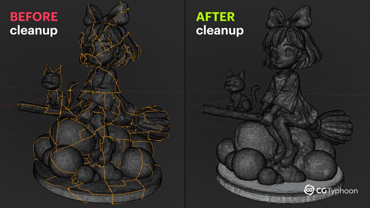
After exporting the model from 3D AI Studio, I received a .glb file and imported it into Blender.
The first step was a basic mesh cleanup pass.
Merge by Distance
AI-generated meshes often contain:
- duplicate vertices
- overlapping points
- broken edges
To clean these issues, I used:
Mesh → Clean Up → Merge by Distance
(INSERT: screenshot of Merge by Distance settings.)
Even a basic vertex cleanup noticeably improved the condition of the topology before moving on to further work.
Delete Loose
The next issue involved:
- floating vertices
- disconnected edges
- loose geometry
To remove these artifacts, I used:
Mesh → Clean Up → Delete Loose
This command removes geometry elements that are not connected to the main mesh.
Checking the Mesh
I also performed several additional checks:
- normals
- non-manifold geometry
- watertight mesh integrity
For FDM printing, the model should be as clean, stable, and watertight as possible.
Quick Blender Cleanup Checklist
✅ Merge by Distance
✅ Delete Loose
✅ Check Normals
✅ Detect Non-Manifold Geometry
✅ Verify Watertight Mesh
Fixing and Polishing the Model in ZBrush
After Blender cleanup, the model was imported into ZBrush.
This is where the longest stage of the project began.
The primary goals were to:
- fix generation errors
- improve the silhouette
- improve the model’s structural stability
- prepare the model for FDM printing
As an experiment, I initially decided to test the fastest possible workflow: generate the model and send it straight to the printer with little to no additional preparation. Although the risks were obvious, I wanted to see how far a modern AI-generated model could go without manual intervention.
As expected, problems started to appear fairly quickly. The large number of overhangs combined with an unfavorable center of gravity made the model increasingly unstable during printing. As the print grew taller, the supports were subjected to greater stress, vibrations became more noticeable, and the overall stability of the model gradually deteriorated.
Eventually, it became clear that the model needed additional preparation before it could be printed reliably. The layout of individual elements had to be reconsidered, connection points needed to be planned, and the figurine had to be split into separate printable parts.
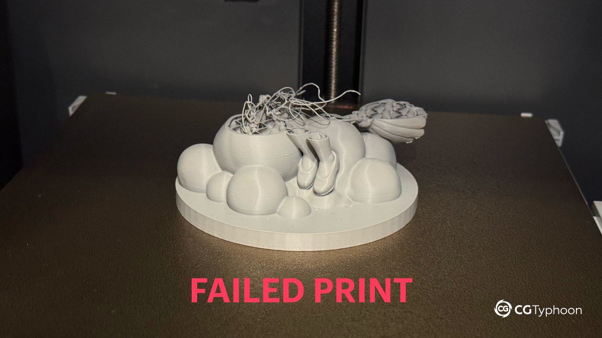
At that point, it became obvious that the model needed to be reworked to accommodate the real-world limitations of an FDM printing workflow.
Part 3. Preparing for FDM Printing
Why I Chose FDM Printing
Most AI-to-3D workflows showcased online are demonstrated using resin printers.
For this project, however, I specifically wanted to test an FDM-based workflow for several reasons:
- more affordable hardware
- relatively inexpensive materials
- a simpler and more accessible printing process
- faster turnaround times
- stricter requirements for model preparation
FDM printing is also very effective at exposing geometry issues that may go unnoticed during modeling or rendering. For that reason, it served as a useful test of how well the model was actually prepared for real-world printing.
| Resin Printing | FDM Printing |
|---|---|
| Better at capturing fine details | More affordable hardware |
| Layer lines are less visible | Lower material costs |
| Commonly used for figurines | Accessible to most hobbyists |
| Requires handling liquid resin | Simpler and safer workflow |
| More forgiving of thin details | Less forgiving of geometry problems |
Preparing the Model for Printing
Before printing, several factors had to be taken into consideration:
- center of gravity
- support placement
- printable overhang angles
- silhouette stability
- geometry thickness
- unsupported areas
Flying poses and dynamic compositions are particularly challenging because a significant portion of the model’s mass is often located far from its primary support point.
Splitting the Figurine into Parts
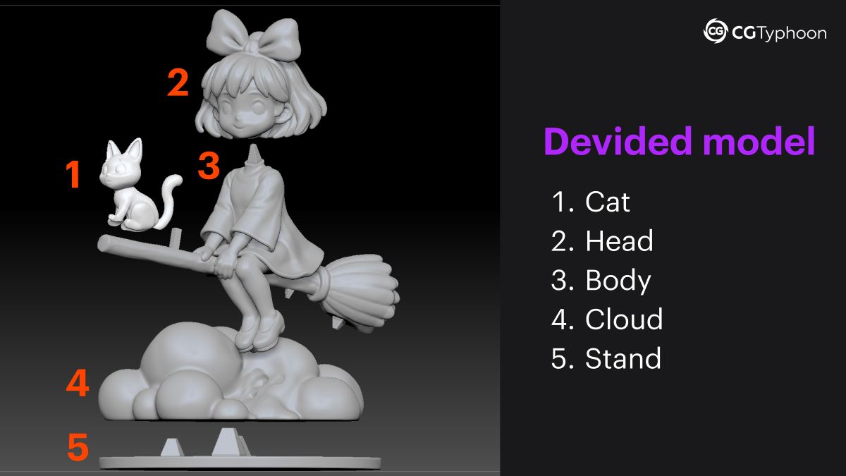
After the first failed print, it became clear that the figurine needed to be divided into separate printable parts. The main reasons were the large number of overhangs, the complexity of the composition, and the difficulty of painting certain areas after assembly.
Before making any cuts, I planned the splitting strategy for the entire model.
The first piece I separated was the cat. It was one of the least stable parts of the composition and would have required a large amount of support material during printing.
I initially kept the main character and the broom as a single piece. Later, however, I decided to separate the head as well. The head was relatively large, while its only connection to the body was the character’s thin neck. Printing it as a single piece would have required supports extending almost to the top of the model, increasing material usage and making the print less stable.
The clouds and base were also separated into individual parts. Besides simplifying the printing process, this made painting significantly easier. If printed as a single piece, many areas would have been difficult to reach with a brush or airbrush.
To separate the model, I used standard ZBrush tools. By combining polygon masking, duplicated SubTools, and the Delete Hidden function, I gradually isolated and extracted each individual part.
After splitting the model, another issue became apparent. Since the original composition had been generated as a single object, some areas of the character were partially embedded inside the cloud. Portions of the arm, leg, dress, and broom simply did not exist because they were never visible in the original mesh. Once the pieces were separated, these missing sections had to be manually sculpted and reconstructed.
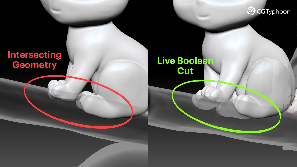
Digital Geometry Can Intersect. Physical Parts Cannot.
Intersecting geometry is perfectly acceptable in a digital model. During modeling, it is common practice to slightly sink one object into another to hide seams or simplify a composition.
Once the model is split into physical parts, however, this approach no longer works. Every component must have a real physical shape and must be able to fit together correctly after printing.
This became particularly obvious in this project. The character and broom were partially embedded inside the cloud, so after separating the pieces I not only had to reconstruct missing geometry, but also redesign the contact areas to ensure that every part could physically fit together while preserving the original appearance of the composition.
For several operations, I used Live Boolean. For example, when separating the head from the body, I created a cutting plane using a thin cube and generated two clean individual parts.
I also used Live Boolean to subtract a portion of the broom geometry from the cat mesh, creating a more natural and secure contact surface once the printed parts were assembled.
Ultimately, splitting the model simplified every stage that followed:
- printing individual parts
- support placement
- post-processing
- painting
- final assembly
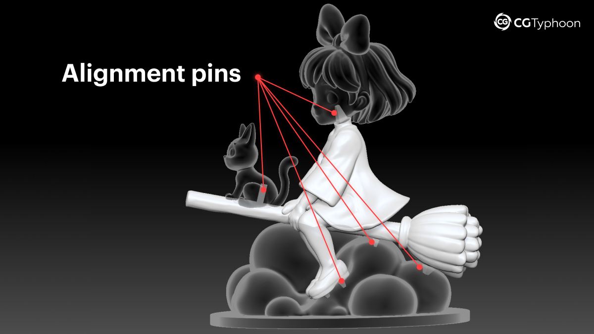
Adding Alignment Pins
After splitting the model, I added alignment pins at the connection points between parts.
These serve several purposes:
- simplify assembly
- improve alignment accuracy
- strengthen glued joints
Alignment pins are especially useful when working with:
- arms
- legs
- accessories
- other thin elements
Creating Assembly Tolerances
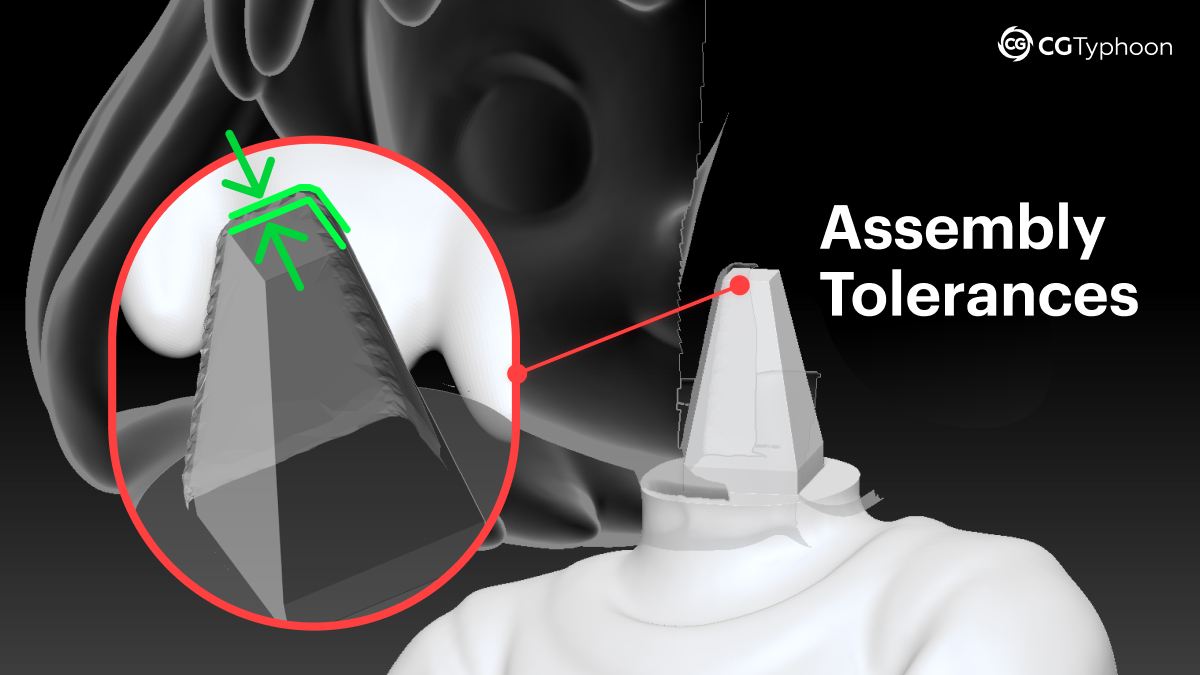
To ensure that printed parts fit together properly, assembly tolerances need to be built into the model.
To create those tolerances, I:
- duplicated the connecting parts
- applied Dynamesh
- slightly expanded the geometry using Inflate
- subtracted the enlarged meshes from the original model
This created the small clearance required for the printed parts to fit together reliably.
As a final optimization step, I also used Decimation Master to reduce polygon density and improve performance when exporting and processing the model.
Part 4. Printing Workflow
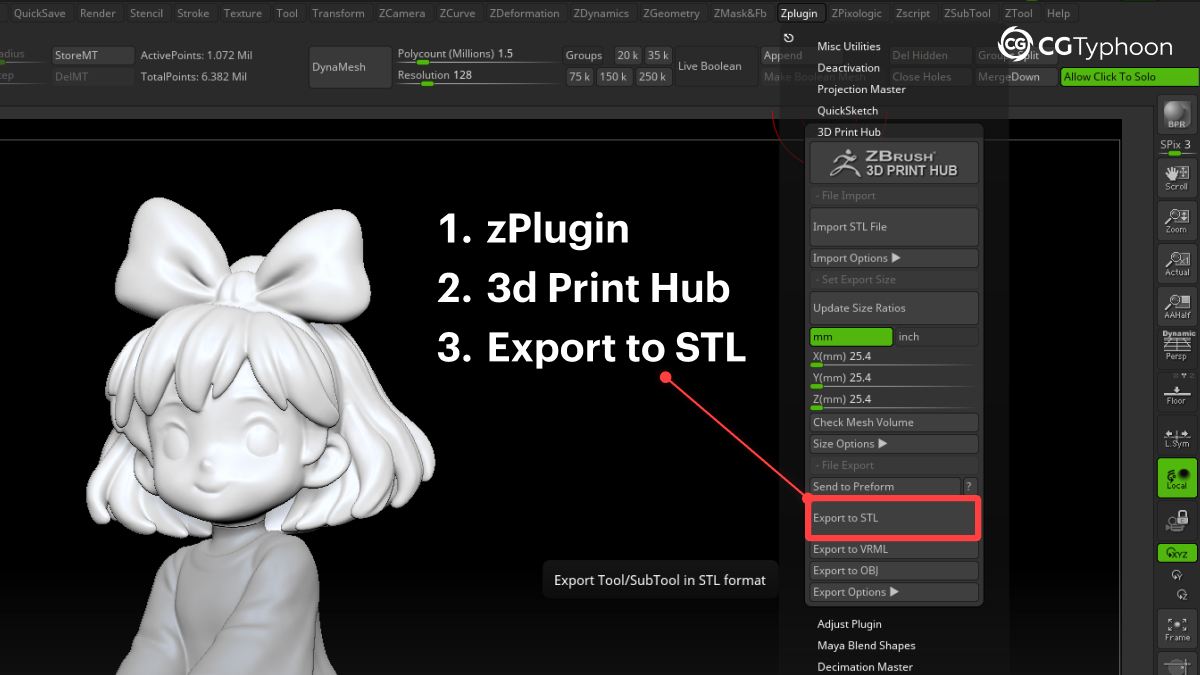
Exporting STL Files
Once all modeling and preparation work was complete, I exported every part as an STL file using:
ZPlugin → 3D Print Hub → Export STL
STL remains the standard format for:
- slicing
- printable geometry
- FDM printing workflows
Slicing in Bambu Studio
For slicing and print preparation, I used Bambu Studio.
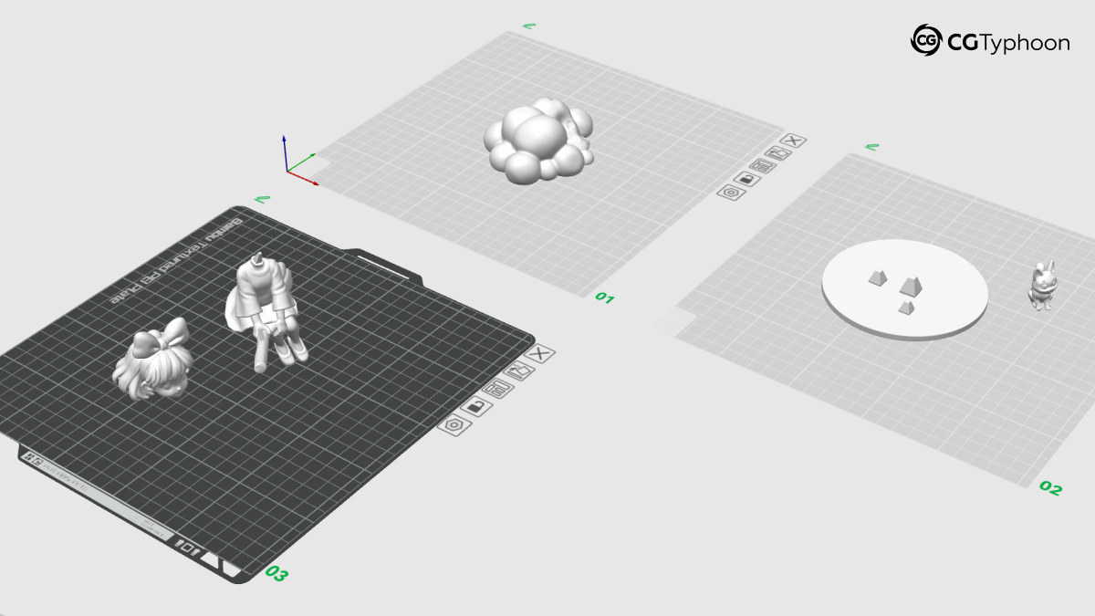
After splitting the figurine into separate components, each part was placed on its own build plate and printed individually. This proved to be far more practical than attempting to print the entire composition at once.
In fact, during the print of one of the larger parts, I unexpectedly ran out of filament, causing the printer to continue printing in mid-air for a short period. Had the model been printed as a single piece, I would have had to reprint the entire figurine. By separating the model into multiple parts, only one component was lost, significantly reducing the impact of the failure.
This approach also made it easier to minimize support material and optimize the orientation of each part independently.
Another advantage was the ability to print different components using different filament colors. For example:
- the cat and the base were printed in black PLA
- the cloud was printed in white PLA
- the character was printed in neutral gray PLA
This reduced the amount of painting required later on. The gray filament also served as an excellent base for acrylic paints, providing a neutral surface that would not affect the final color appearance.
Before printing, I adjusted the orientation, support settings, and infill density for each part individually. This resulted in a much more stable printing process and helped avoid several of the issues encountered during my first attempt at printing the model as a single piece.
Printing Settings
The model was printed on a Bambu Lab P1S using the following settings:
- Layer Height: 0.12 mm High Quality
- Supports: Automatic
- Sparse Infill: 6–10%
- Material: PLA
For larger parts, I used lower infill values to reduce both print time and material consumption without significantly affecting strength.
Printing and Assembly
After several hours of printing, all parts were ready for assembly.
Before final assembly, the remaining work consisted of removing supports, lightly sanding a few areas, and making minor adjustments to several connection points where necessary.
Thanks to the planned model separation and the alignment features added during preparation, post-processing was significantly easier than it would have been with a single-piece print. Individual components were easier to clean, paint, and handle without risking damage to neighboring parts.
Once every piece had been test-fitted, the final step was simply assembling the figurine and verifying that all major elements aligned correctly.
Part 5. Results & Lessons Learned
Final Result
Despite the number of fixes and refinements required throughout the process, the final result turned out far better than I initially expected.
I was able to complete the entire journey from an AI-generated concept to a physical figurine using the following toolset:
- ChatGPT
- 3D AI Studio (Prism 3.1)
- Blender
- ZBrush
- Bambu Studio
- Bambu Lab P1S
The project highlighted both the strengths of modern AI tools and the challenges that still require manual work.
Perhaps the most rewarding moment was seeing a concept that had existed only as an AI-generated image a few days earlier transformed into a real physical object. While manual cleanup and refinement were still necessary, today’s tools can dramatically shorten the distance between an idea and a finished figurine.
AI dramatically accelerates ideation and base mesh creation, but turning a generated model into a printable asset still requires strong traditional CG skills.
What I Learned from the Workflow
The biggest takeaway from this project is that modern AI workflows rarely look like this:
Concept → Generate → Print
In reality, the process is much closer to:
Concept → Generation → Cleanup → Topology Fixes → Print Preparation → Slicing → Testing → Assembly
AI tools genuinely make it much faster to move from an idea to a usable base model. Tasks such as concept generation, exploration, and initial mesh creation can now be completed in a fraction of the time they would have required only a few years ago.
However, the fundamentals remain just as important as ever.
This is especially true when it comes to:
- topology
- mesh cleanup
- support planning
- printable geometry
- slicing
- print preparation
Modern generators are already excellent starting points for a 3D production pipeline. They can save a tremendous amount of time during the early stages of a project. Yet it is still the manual cleanup, refinement, and technical preparation that transform a generated mesh into a reliable, production-ready asset.
Frequently Asked Questions (FAQ)
Can AI-generated models be 3D printed directly?
Which AI tool produced the best result in this project?
Among the free tools I tested, 3D AI Studio (Prism 3.1) produced the most usable base mesh and required the least amount of cleanup before moving into Blender and ZBrush.
Why didn't you print the figurine as a single piece?
The original one-piece print failed because of large overhangs and an unfavorable center of gravity. Splitting the model into multiple parts reduced support requirements, improved print stability, and made painting much easier.
Why use Blender if the model was edited in ZBrush later?
Why were alignment pins necessary?
What is assembly tolerance in 3D printing?
Why choose FDM instead of resin printing?
What file format was used for printing?
Do AI tools replace traditional 3D modeling skills?
Would creating front, side, and back views improve image-to-3D results?
Conclusion
For me, this project demonstrated that AI is not a replacement for traditional 3D skills—it is a powerful accelerator. The better your understanding of modeling, topology, sculpting, and 3D printing fundamentals, the more effectively you can turn generated results into finished physical products.